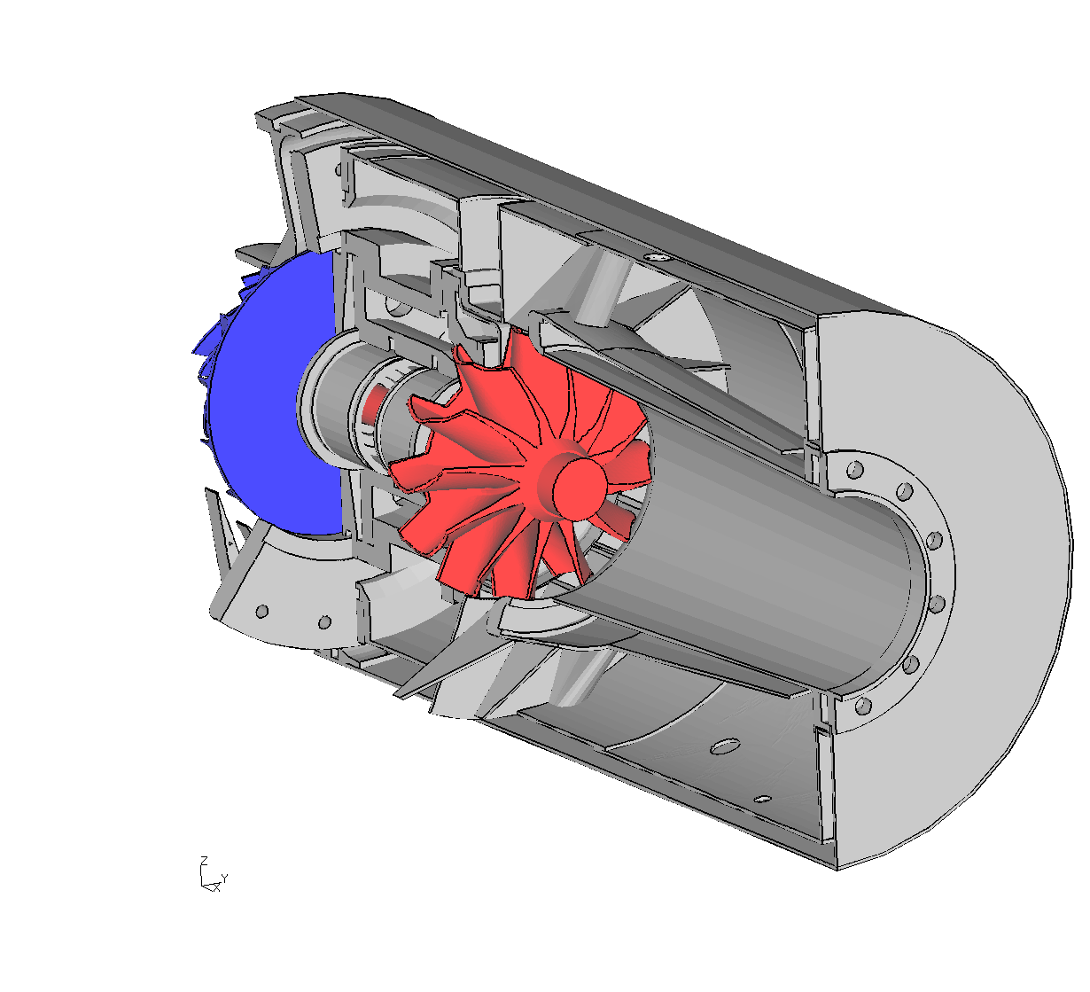
Rear
view of the jet-engine FE-model
Click here to get
The package includes a 3D- and a 2D model. There are no boundary conditions
applied on the 3D model. The intention is to give insight in
the way cgx deals with geometry and how certain parts are designed in cgx. The
2D model was derived from the 3D model and includes all necessary boundary
conditions and the solver file for a thermal calculation.
Some documentation of the jet-engine project is available. The documentation is in German
language. The first part lists the specification, gives technical background
of the engine and explains the detailed anaytical design of all components. The
testing of the real engine is documented in the three build-reports.
Photos of the test-bed and of the disassembled engine can be found in the
documentation of the second build.
A 2D thermal model was created based on the formulas and results as stated in the
documentation listed above:
Time dependent temperatures [K]. 2D-model with 1D-thermal network.
From cold to full rated in 3 sec, then 117 sec at full rated conditions.
(This is an animated gif file)
The 2D thermal results were mapped on the 3D model:
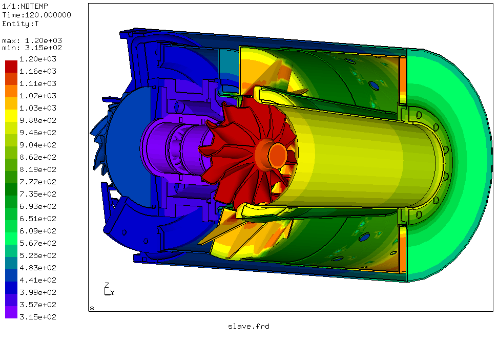
Mapped temperatures [K], after 117 sec at full rated conditions.
PrivacyPolicy
Legal Disclosure