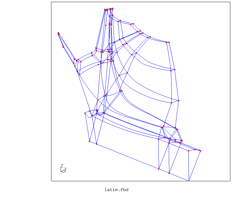
Picture 1. Wireframe of the turbine section
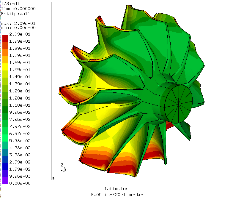
Picture 2. Pressure [MPa] due to 110000/min rotational speed, calculated with ccx_2.2 (CFD) based on a simplified 3D-model and interpolated to the fe-model. It was interpolated to just one sector before it was expanded to 360 degree by multiple copy operations.
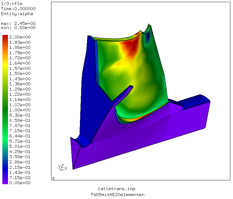
Picture 3. Heat transfer coefficients [N/s/mm/K] due to 108000/min rotational speed, calculated with duns (CFD) based on a simplified 3D-model (Twall:600K, Tin_rel:1085K).
Picture 4. Instationary temperature distribution [K] during acceleration from ambient temperature in 3 sec, about 2 minutes at constant speed of 110000/min at 1200K Ttot, decelleration to cold state and again accelleration to 110000/min (This is an animated gif file).
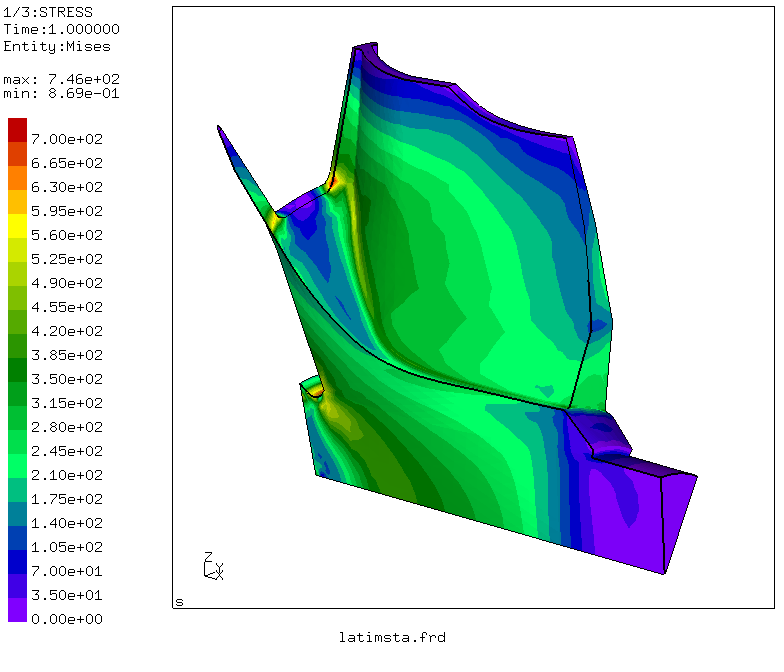
Picture 5. Von Mises stress [MPa] due to 110000/min rotational speed, thermal strains and pressure load.
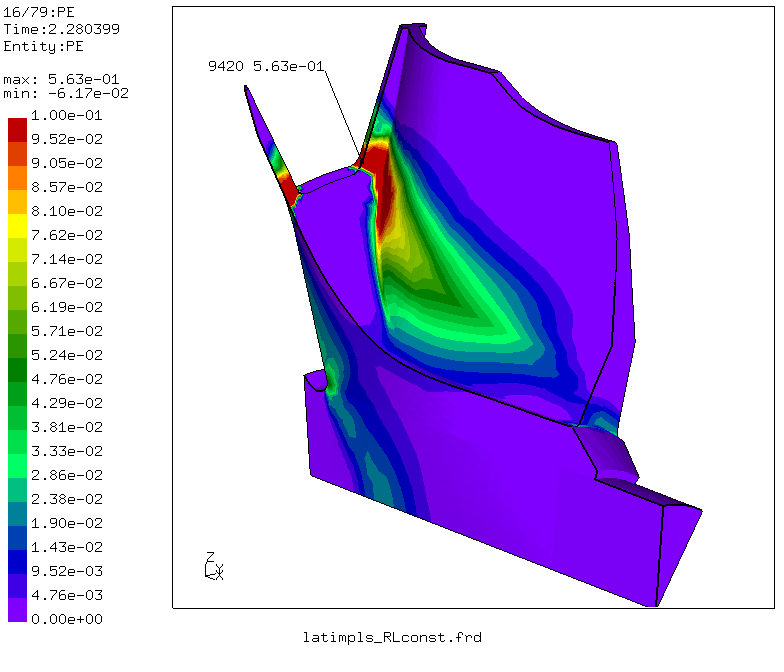
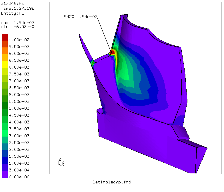
Picture 6. Equivalent plastification at the last converging time-step of the burst calculation at about 165000/min.
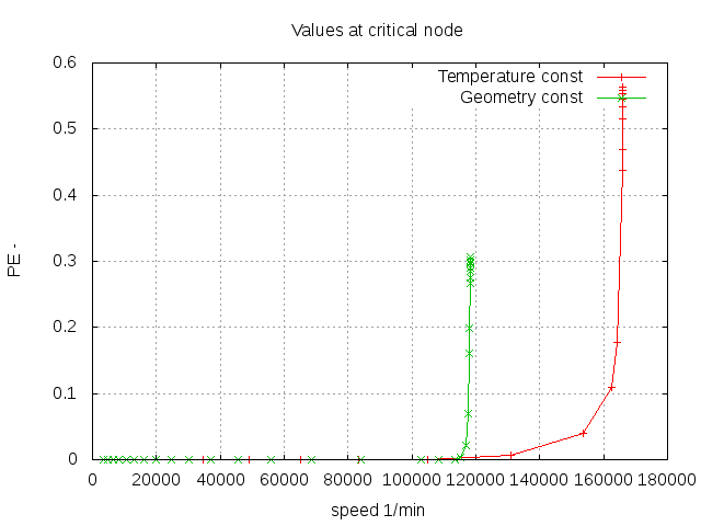
Picture 7. Equivalent plastification vs. rotational speed. Two results are shown: The green line shows the situation when pressure and temperatures increase with speed² (happens for a fixed geometrical configuration when just more and more fuel is supplied). The red line shows the situation when the temperature is constant (the nozzle area increases accordingly). In the first case save operation is possible below 116000/min and in the other case 160000/min are still save.
Picture 8. Equivalent creep strain after slightly more than 1h of operation at 110000/min. CalculiX provides an interface for user-written subroutines which was used for this calculation.
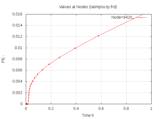
Picture 9. Equivalent creep strain in the blade at 110000/min over time.
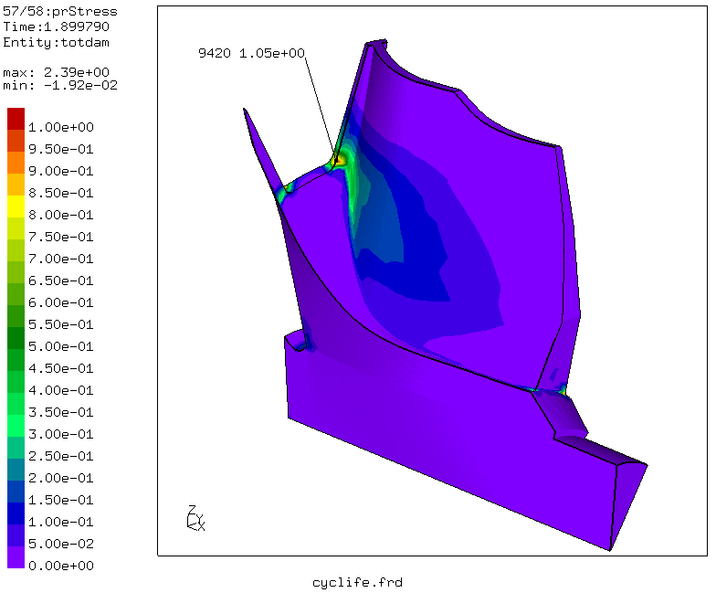
Picture 10. Combined damage of LCF and creep strain after about 2h and 60 cycles of operation. Every cycle lasts 2 minutes. Save operation is possible under this conditions for just about 1 hour and 30 fast cold starts!
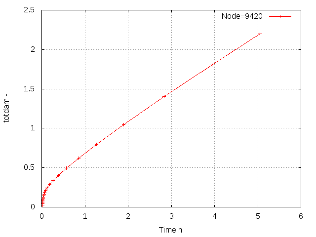
Picture 11. Combined damage of LCF and creep strain in the blade over time.
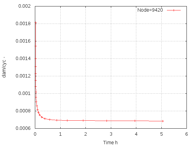
Picture 12. Combined damage per cycle of LCF and creep strain over time. The damage per cycle decreases and stabilizes after some minutes.
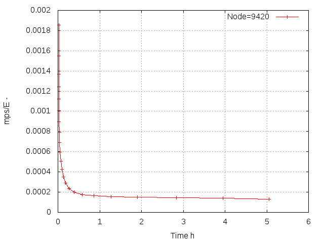
Picture 13. Mean stress divided by Emodulus over time. The decreasing mean stress at the failure location caused by plastification and creep explains the decreasing damage per cycle.
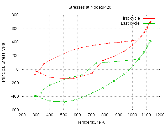
Picture 14. Stress over temperature for the first and last cycle after 5h of operation. The mean stress shift is clearly visible.
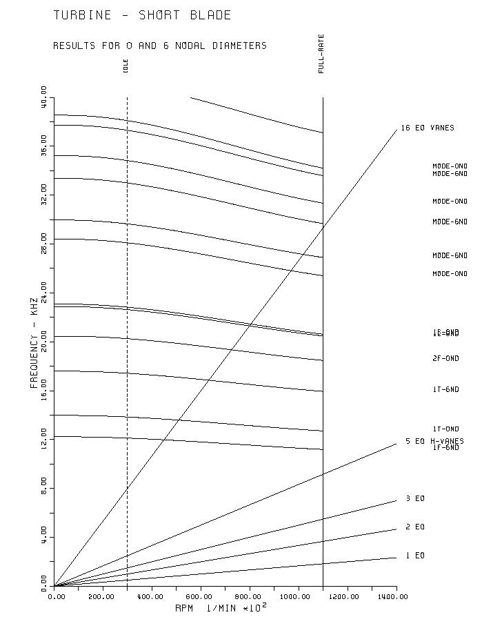
Picture 15. Frequency diagram of the turbine-blades. Resonances with the vanes can not be avoided. Stress stiffening due to the rotational force and the increase in temperature with the rotational speed is considered.
Picture 16. Modeshape of the first bending mode with five nodal diameters (1F-5ND). This mode could be triggered by the five hollow vanes used in the gas-turbine. For this calculation the cyclic symmetry capabillity of CalculiX was used.
Click HEREto see more about the finite element and graphic capabilities of CALCULIX